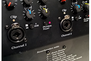
Jack input/XLR input/Combo input
These are connection sockets on amplifiers or mixers. Jack and XLR are types of audio connector. I will start off by describing the jack plug, i.e. the part that goes into the jack input. The reason for this is that you can see the plug, the socket is internal and it is not possible to see the connection parts which help to define the type of jack socket it is. The jack connector is generally a barrel with a small metal rod sticking out, this rod has one or 2 bands round it, often black but they can be red or any other colour. These are insulators which in turn produce 2 or 3 silver connector parts. If there are 2 silver parts, i.e., just one black insulator part, then the jack is called a mono jack which means it provides connection for just one audio signal. If there are 2 black insulating rings so producing 3 silver connector parts then the jack is a stereo connector and provides 2 audio signal connections. Just to be a little more confusing, a stereo jack is also used for a balanced signal where one audio signal uses 2 audio connections. You can read more on balanced connectors later or in another post.
A jack connector, both socket and plug, come in 2 physical sizes, 3.5mm and 6.3mm often call ¼”. 3.5mm jack plugs are most often used for outputs, e.g. headphone output, portable CD player output. There is however no reason why they cannot be used for inputs as well.
A jack socket looks very simple on any mixer or amplifier. It is simply a round hole, 3.5mm or 6.3mm in diameter, usually with a metal or plastic nut holding it in place but some may not have this nut. There is no way of telling if the socket is mono or stereo, if it is an input then no damage will occur by plugging in a mono jack to a stereo socket, you will just get a single channel and not the expected stereo. Slightly more care needs to be taken when plugging in a stereo jack into a mono socket as one channel of the stereo jack will shorted to ground which may not be good for the device to which the jack is connected.
XLR connectors are 3 pin, they can be more but for most audio work they are 3 pin, devices. If used correctly you can consider the audio signal flowing in the direction of the pins. Therefor if you have a male connector, i.e. one with 3 pins you can see then the connector is an output. If the connector has 3 hols, where the pins would go, then it is an input. Although there is not regulations regarding how any connector is wired up, XLR connectors generally are a single audio signal device, even with the 3 pins only one audio signal is present. XLR connectors are generally used for balanced signals which mean that one of the pins, pin 1, is ground and pins 2 and 3 are both the audio signal however they are out of phase to each other. You can read about balanced signals in another post but here we will just accept that being out of phase to each other not only doubles the level of the signal but also greatly reduces the likelihood of interference. For this reason, XLR connectors are favoured for the connection of microphone signals or other low level audio signals.
In addition to carrying the audio signal, XLR connectors often also carry what is called phantom power. This is a DC voltage up to 48v which is used to power the microphone of other audio equipment connected to the XLR cable. Only a limited amount of current is available form this phantom power, 10mA per leg for those interested, so it cannot be used for much more than powering a simple handheld microphone. Phantom power is usually only available from a mixer and is usually switchable so may be switched off if not required. 48v was the original standard for phantom power but now low voltage versions may be found, usually no lower than 12v.
There are a relatively new version of input socket available these days, the combo socket and as the name suggests it is a combination of the Jack and XLR connector so either may be used. To look at it has a single 6.3mm hole in the centre and 3 smaller holes round the edge, these smaller holes run into the 6.3mm central hole. These sockets are particularly convenient as they offer a greater range of input possibilities without increasing the size of the input panel. It should be noted however if an input can provide phantom power, this will only be available through the 3 pins of the XLR connector, it will not be available through the jack socket part of the same connector.
Generally speaking, when you are using a low signal level microphone you should connect it to a XLR connector input and if you are using a higher-level signal then it can be used in either type of socket. The overriding issue will however be down to the equipment manufacturer and how they have designed the input circuitry for each type of connector.

